
SharpEye-LR20
Long Range Observation System
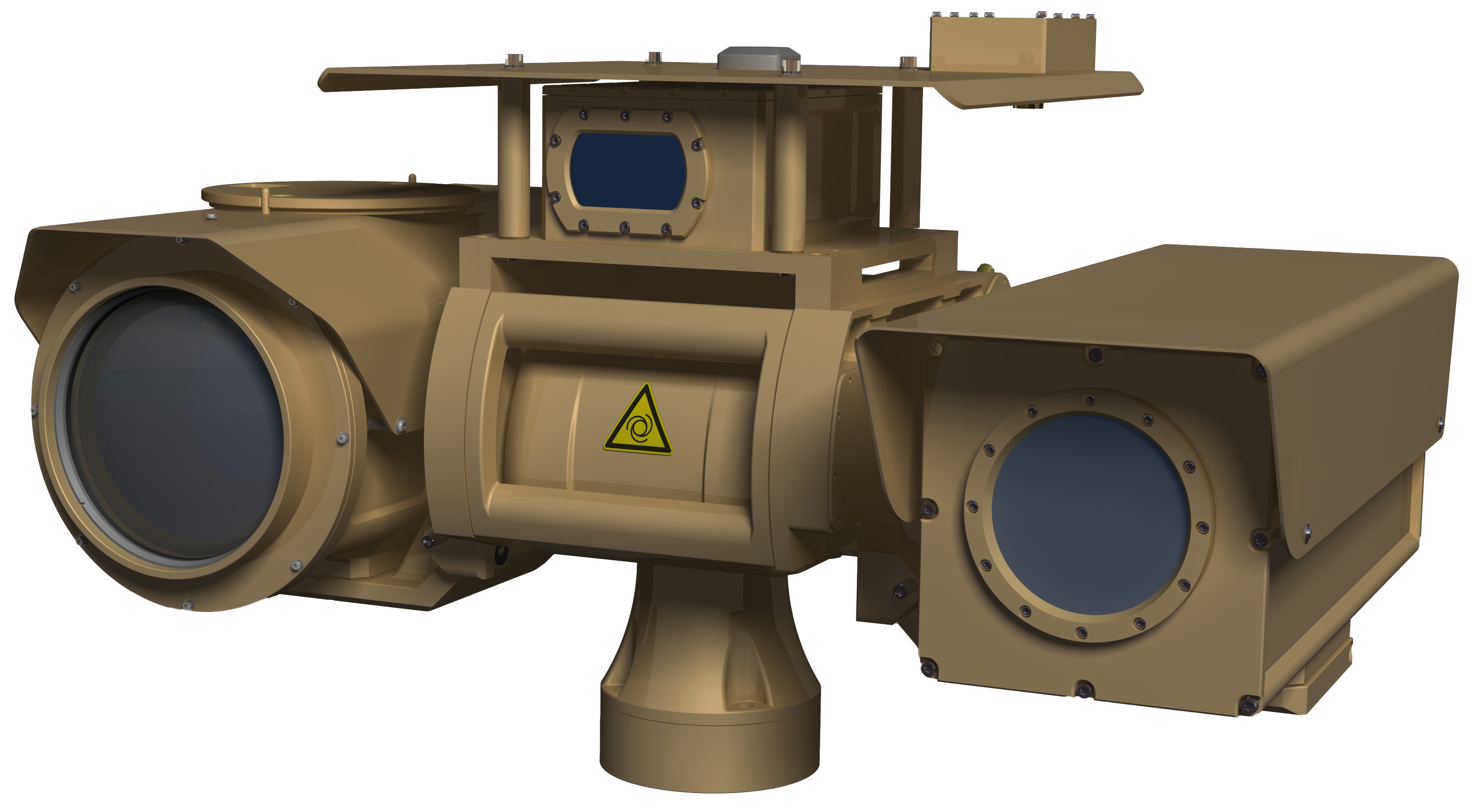
SharpEye-LR20 is a long-range observation system purpose-built for continuous, 24-hour surveillance in the harshest field and maritime conditions. A protective roof shields the electro-optical head against rain, fog, and direct sun, while the cooled MWIR thermal camera, HD visible camera, and laser rangefinder are all bore-sighted for precise, coordinated target acquisition.
Built to operate reliably from -32°C to +65°C, the system is fully sealed against sea spray, rain, sand, dust, and corrosion — making it suitable for demanding maritime and land border environments alike.
For missions requiring geo-referenced situational awareness — such as air traffic control support, border control, and search & rescue — SharpEye-LR20 can optionally be equipped with a two-axis pan-tilt platform paired with a Digital Magnetic Compass (DMC) and GPS, allowing map data to be overlaid directly onto the live picture.
System Comprises:
- Two-axis Pan-Tilt Mechanism Platform
- HD Visible Camera with 60x Optical Zoom Lens
- Cooled MWIR Thermal Camera with Continuous Zoom
- Laser Rangefinder — measurement range up to 20 km
- Digital Magnetic Compass (DMC) — for map orientation
- GPS Unit — for real-time position and map overlay
- Dual-Screen Operator Console Station
- GUI Control Software with Observation, Scanning, and Tracking modes
◆ Pan-Tilt Mechanism
The two-axis Pan/Tilt uses a “T”-shaped mechanical carrier arrangement, driven by two alternating servo drives for smooth rotational movement in both horizontal and vertical planes. It is controlled over Ethernet (TCP/IP), allowing full command of servo drives, sensor systems, and user I/O from the control station.
| Parameter | Value |
|---|---|
| Azimuth movement range | n × 360° (continuous) |
| Elevation movement range | ± 40° |
| Azimuth speed range | 0.03°/sec to 70°/sec |
| Elevation speed range | 0.03°/sec to 70°/sec |
| Repeatable position precision | ≤ ± 0.5 mrad (Azimuth, Elevation) |
| Payload | 2 × 17 kg (balanced) |
| Pan-Tilt control interface | Ethernet 100/10 Mbit, TCP/IP |
| Sensors interface | 5× Serial Line + 1000 BASE-T TCP/IP |
| Power supply | 24 V DC (20–30V) |
| Consumption | 75 W (typical, without sensors) |
| Operating temperature | -32°C to +65°C |
| Environmental protection | IP66 |
| Weight (platform only) | 18.5 kg |
| Weight (with all sensors) | < 25 kg |
◆ HD Visible Camera
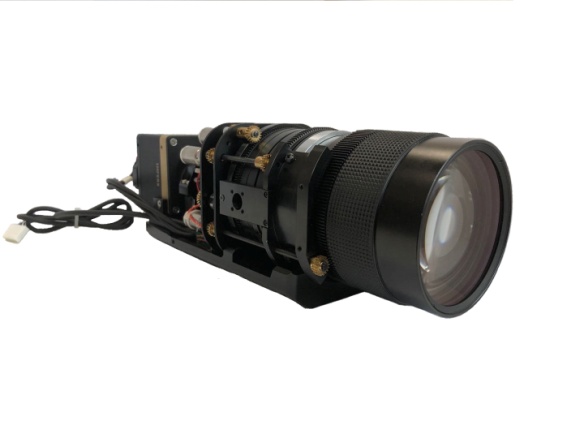
A highly sensitive color camera with a 60x optical zoom lens, offering both wide and telephoto fields of view, plus a 2x extender for extended-range observation. Equipped with a 1/3″ Color CMOS sensor and Auto ICR function for optimized day/night sensitivity, along with Auto Focus, Backlight Compensation, Auto Iris, Automatic Gain Control, and Video Motion Detection. Ruggedized to perform across a wide temperature range in any weather condition.
| Parameter | Value |
|---|---|
| Image device | 1/3″ Colour CMOS |
| Spectral range | 400nm to 1000nm |
| Picture elements | 1920(H) × 1080(V) |
| Digital output | HD-SDI |
| Minimum illumination | 0.031 lux (Color mode, 30 IRE) |
| Focal length | 15.6 – 500mm (32x) |
| Angle of view (wide) | 18°34′ × 10°29′ |
| Angle of view (tele) | 0°36′ × 0°22′ |
| Control interface | RS232/RS422 |
| Power supply | 24 V DC |
| Consumption | 20 W typical / 85 W (heater normal) |
| Operating temperature | -32°C to +55°C |
| Environmental protection | IP66 |
| Weight | < 3 kg |
| Size | L: 198 × D: 520 × H: 184 mm |
◆ Cooled MWIR Thermal Camera
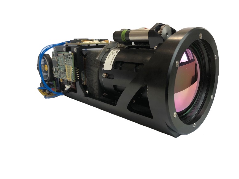
Equipped with a highly reliable, cooled Middle-Wave MCT detector for reliable mid-range detection in all weather conditions. The continuous zoom lens delivers strong situational awareness, allowing operators to zoom in on suspect activity once detected.
| Parameter | Value |
|---|---|
| Detector type | Cooled Middle Wave MCT, 640×512 pixels |
| Spectral range | 3 to 5 μm |
| Thermal sensitivity | < 25 mK |
| Image processing | Digital Detail Enhancement (DDE), Histogram Equalization |
| Digital output | HD-SDI |
| Focal length | 30 – 660 mm |
| Angle of view (wide) | 18.1° × 14.5° |
| Angle of view (tele) | 0.85° × 0.68° |
| Optical zoom | Continuous, 20x |
| Control interface | RS232 |
| Power supply | 24 V DC (18–32V) |
| Consumption | < 25 W typical / < 35 W max |
| Operating temperature | -32°C to +55°C |
| Environmental protection | IP66 |
| Weight | < 3 kg (including housing) |
| Size | L: 203mm × W: 650mm × H: 227mm (including housing) |
◆ Laser Rangefinder
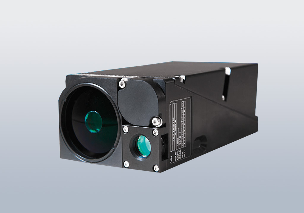
An eye-safe, modular laser rangefinder purpose-built for vehicle-based observation and fire control systems. Depending on weather and target characteristics, range measurement extends from 80m to over 20 km, with an accuracy of ± 1m.
| Parameter | Value |
|---|---|
| Wavelength | 1.54 μm |
| Range of measurement | 80 to 20,000 m |
| Range accuracy | ± 5 m |
| Eye-safety | Fully eye-safe, Class 1 |
| Control interface | RS422 |
| Power supply | 24 V DC |
| Consumption | 5.6 W typical / 20 W max |
| Operating temperature | -32°C to +55°C |
| Environmental protection | IP66 |
| Weight | < 0.6 kg |
Detection, Recognition & Identification (DRI) Range
Calculated per Johnson Criteria (Detection 0.75 cycles, Recognition 3 cycles, Identification 6 cycles), atmospheric attenuation per STANAG 4347, extinction coefficient 0.95 km⁻¹.
| Standard NATO Target | Task | 1280×1024 (0.4dB/km ext.) | 640×512 (0.4dB/km ext.) |
|---|---|---|---|
| Person (1.8m×0.5m, ΔT=2°C) | Detection | 12 km | 10 km |
| Recognition | 4.2 km | 2.6 km | |
| Identification | 2.1 km | 1.5 km | |
| Tank (2.3m×2.3m, ΔT=5°C) | Detection | 17 km | 16 km |
| Recognition | 10 km | 8 km | |
| Identification | 6 km | 4 km | |
| Boat (5m×3m, ΔT=6°C) | Detection | 22 km | 20 km |
| Recognition | 11 km | 10 km | |
| Identification | 5.5 km | 5 km |
◆ Compass Unit (DMC)
The Digital Magnetic Compass (DMC) functions as the system’s north sensor — a solid-state module providing azimuth and elevation angle data.
| Parameter | Value |
|---|---|
| Azimuth accuracy | 0.8° |
| Tilt accuracy | 0.2° (-50° to +50°) |
| Sample rate | 20/sec |
| Control interface | RS232 |
| Power supply | 12 V DC |
| Consumption | 0.5 W typical |
| Operating temperature | -32°C to +55°C |
| Environmental protection | IP66 |
| Weight | < 0.8 kg |
◆ GPS Unit
Included as a printed board receiver module, providing real-time position tracking. Results are displayed directly on the operator console; the GPS antenna is mounted on the vehicle roof.
| Parameter | Value |
|---|---|
| Receiver type | L1 frequency, C/A Code, 16-channel |
| Output | Latitude, Longitude, Altitude, Time |
| Max. update rate | 1 Hz |
| Position accuracy | 4 m CEP (SA Off) |
| Control interface | RS232 |
| Power supply | 5 V DC |
| Consumption | 0.5 W typical |
| Operating temperature | -40°C to +70°C |
| Environmental protection | IP65 |
◆ Console Station
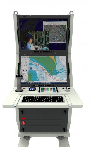
A dual-32″ screen console with controlling box and joystick, providing a comfortable and powerful control interface between the operator and all installed sensors. Supports manual, semi-automatic, and fully automatic operation.
| Parameter | Value (minimum specification) |
|---|---|
| CPU | Intel Atom quad-core, 2.6 GHz, 533 MHz FSB, 16GB L2 cache, Hyper-Threading |
| RAM | 4 GB |
| Storage | 16 TB HDD |
| Networking | Ethernet 10/100/1000 Mbit/s |
| Ports | 2× Serial ATA, 4× USB 2.0, HD-SDI, RS422, 2× RS232 |
| Power supply | 24 V DC |
◆ GUI Software
The GUI STANDARD software package gives operators intuitive, independent control of each sensor payload from the main control computer.
Standard Modes
- Observation mode — manipulator control via joystick, image click, position dials, or panorama click
- Fast options — one-touch buttons for laser measurement, video recording, photo capture, full-screen mode, and reticle toggle
- Panoramic image — 160° to 360° panorama display (screen-resolution dependent), with switching, deleting, and creation controls
- Scanning mode — fully automatic cyclic surveillance of a defined area
- Media management — photo/video capture and storage, including alarm snapshots, accessible as standard data
Optional Modules
- Alarm mode — motion detection within the active camera’s field of view
- Tracking mode — automatic tracking of an operator-selected object of interest
- North searching (DMC) — automatic north-finding via the Digital Magnetic Compass
- GPS reading — live position, satellite count, latitude/longitude display
- Digital Image Stabilization — compensates unwanted camera vibration
- Vector Maps — zoomable vector map with live position, FOV, video direction, and laser-measured target coordinates
- Lifting control — for vehicle-mounted installations, lift mechanism control from the GUI